

Process Cooling Systems for Automotive and Metalworking
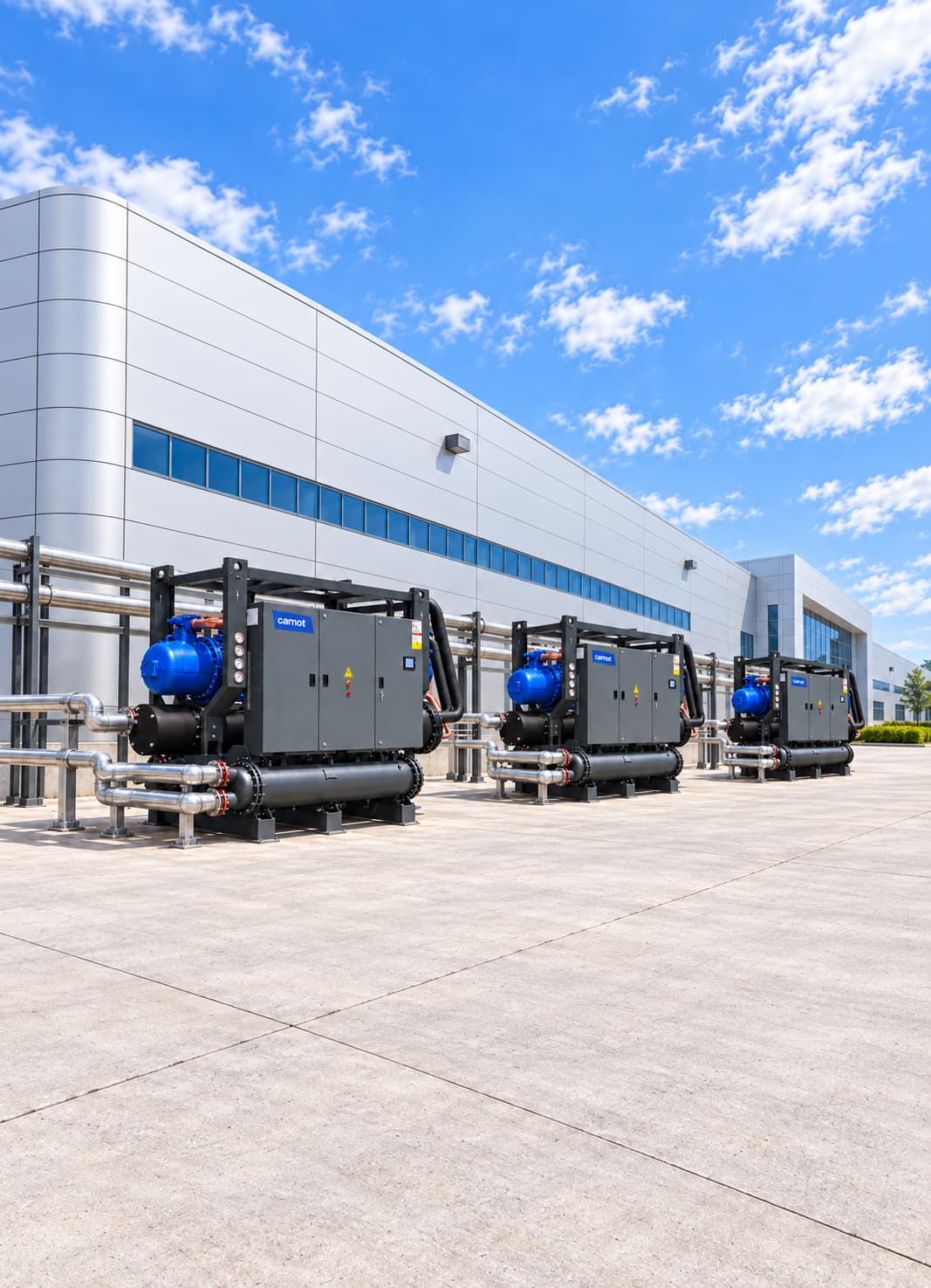
An automotive and metalworking cooling system combines chillers, dry coolers, heat exchangers, filtration and controls to supply CNC spindles, fibre laser sources, welding electrodes, hydraulic units and cutting-fluid circuits at the right temperature and a stable flow rate. Carnot engineers each system for the facility, from machine-maker requirements to production-line redundancy.
Sector Overview & Process Demands
An automotive and metalworking cooling system combines chillers, dry coolers, heat exchangers, filtration and controls to supply CNC spindles, fibre laser sources, welding electrodes, hydraulic units and cutting-fluid circuits at the right temperature and a stable flow rate. Carnot engineers each system for the facility, from machine-maker requirements to production-line redundancy.
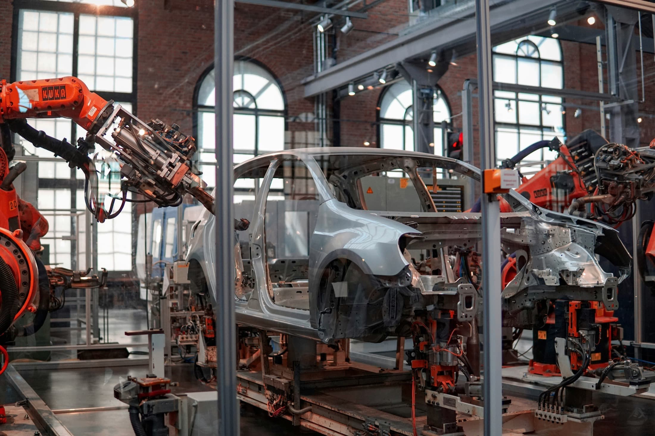
Temperature control in automotive and metalworking plants directly affects machining accuracy, surface finish, tool life and production continuity. If heat from CNC machines, laser cutters, welding systems, press lines, hydraulic units and metalworking fluids is not controlled, dimensional errors, process instability and unplanned downtime can follow.
Carnot develops central and machine-level process cooling systems for automotive manufacturers, suppliers and metalworking plants. Chillers, dry coolers, free cooling, pump and tank groups, filtration and controls are engineered to maintain stable fluid temperature, the required flow rate and high energy efficiency as production loads change.
Critical Operational Requirements
Why Is Cooling Critical in Metalworking?
Heat generated during metalworking raises the temperature of the workpiece, cutting tool, spindle, hydraulic system and cutting fluid. Temperature changes can expand metal parts, distort machine geometry and push dimensions outside machining tolerances. A properly engineered process cooling system keeps machining temperature stable.
- Maintains dimensional accuracy and repeatability.
- Extends tool and spindle life.
- Prevents overheating of cutting fluid.
- It keeps hydraulic oil viscosity under control.
- Protects critical equipment in laser and welding systems.
- Prevents capacity loss during intensive production periods.
- Reduces risk of unplanned downtime and maintenance.
- Limits unnecessary energy consumption in variable loads.
Where Are These Cooling Systems Used?
Each application has different temperature, flow, pressure and fluid requirements. Battery and e-motor test benches may need temperature cycles from −40 °C to +85 °C, using a low-temperature chiller configuration and glycol circuit. Size the system for the actual heat to be removed from the equipment and process, rather than machine electrical power alone.
- Carnot process cooling systems are used in automotive and metal processing applications:
- CNC lathe and machining centers
- Spindle cooling systems
- Fiber laser cutting machines
- Plasma cutting systems
- Welding machines and robotic welding lines
- Spot-welding systems
- Hydraulic presses
- Press and transfer lines
- Cutting oil and emulsion cooling
- Grinding machines
- Heat treatment auxiliary cooling circuits
- Induction systems
- Engine and transmission test benches
- Battery module and pack test benches
- E-motor and inverter test systems
- Battery cell production dry room air conditioning
- Paint and surface finishing processes
- Compressor and vacuum system auxiliary circuits
- Central machine cooling systems
System Design & Capacity Calculation
Engineering & Sizing Criteria
How Is a Metalworking Cooling System Designed?
Assess machine count, simultaneous operation, minimum and peak loads, target temperature, fluid properties and production schedule together. A continuously running CNC line does not have the same load profile as an intermittent press or welding line.
| Design Parameter | Engineering Significance |
|---|---|
Total process load | Determines the required capacity of chiller and auxiliary equipment. |
Target fluid temperature | Determines processing precision and chiller working conditions. |
Temperature stability | Critical for precision CNC, spindle and laser equipment. |
Number of temperature circuits | Determines how laser, spindle, hydraulic and emulsion circuits are separated. |
Design flow | Provides sufficient heat transfer in machinery and exchangers. |
Pressure loss | Affects pump selection and energy consumption. |
Fluid properties and water quality | It determines the selection of heat exchanger, pump, seal and pipe material. |
Simultaneous working rate | Prevents unnecessary high capacity selection. |
Minimum and maximum load | Guides compressor staging and part-load efficiency. |
Ambient Temperature | Determines temperature reference in sensitive processing applications. |
Redundancy requirement | Keeps critical production lines cooled during maintenance or a fault. |
Capacity Calculation & Thermodynamic Formula
How Is Process Cooling Capacity Calculated?
The heat carried by the water circuit is calculated using the following basic equation:
Q = ṁ × cp × ΔT
Worked Engineering Example
For a water circuit, a practical calculation is Q (kW) = 1.163 × Flow (m³/h) × ΔT (°C). If 100 m³/h circulates through a central process loop with a 4 °C inlet-to-outlet difference, Q = 1.163 × 100 × 4 = 465.2 kW. Where machine makers provide cooling requirements, do not simply add every rated value. Check whether machines operate at full load simultaneously and establish the actual simultaneity factor to avoid oversizing.
The theoretical heat load carried by this circuit is approximately 465 kW. Final chiller capacity also accounts for simultaneous machines, pipework heat gains, sudden load changes and planned future expansion.
Energy Optimization
Share your machine list to compare simultaneous loads and central versus local chiller options.
Energy Consumption & Annual Operating Cost Analysis
600 kW Automotive Machining Facility Annual Energy Simulation
Theoretical full-load comparison for an automotive machining line with 600 kW cooling demand operating 5,000 hours/year.
Scenario comparison table
| System | COP | Compressor power | Annual consumption |
|---|---|---|---|
| Reference chiller system | 4.50 | 133.3 kW | 666,500 kWh |
| High-efficiency Carnot system | 5.75 | 104.3 kW | 521,500 kWh |
| Theoretical saving / difference | — | 29.0 kW | 145,000 kWh (21.7%) |
| Annual cost advantage | — | €0.12/kWh | Approximately €17,400 |
Annual Electricity Savings
145,000 kWh
21.7% theoretical reduction in compressor use
Annual Cost Advantage
~17,400 €
Calculated at €0.12/kWh reference electricity rate
Theoretical Power Difference
29.0 kW
Reference COP 4.50 / Carnot COP 5.75
Note: This calculation compares compressor power at 5,000 hours of full load. Actual annual savings will depend on plant load profiles, process temperatures, pump and fan modulation, local weather data, and economizer hours.
Related products
Thule Series Air-Cooled Chiller
Supplies process water or glycol without a cooling tower.
- Capacity
- 2–2,000 kW
- Compressor
- Scroll / screw
Tundra Series Water-Cooled Chiller
Provides stable cooling for high-load central metalworking circuits.
- Capacity
- 30–4,000 kW
- Compressor
- Scroll / screw
ZERO Series Chiller
Uses a low-GWP refrigerant for efficient process cooling.
- Capacity
- 10–1,800 kW
- Refrigerant
- R1234ze
Fusion Series Free Cooling Unit
Reduces compressor operating hours when outdoor conditions allow.
- Capacity
- 15–2,000 kW
- Operating principle
- Free cooling
Kalter Series Dry Cooler
Rejects heat from hydraulic press and welding-transformer circuits to outdoor air.
- Capacity
- 90–1,800 kW
- System
- Dry cooler
Technical Questions About Automotive & Metalworking Cooling Systems
Detailed engineering answers on system sizing, capacity calculations, water temperatures, and Carnot equipment.
Let's engineer solutions tailored to your needs
By analyzing your process and operational data against engineering criteria, we determine capacity, system configuration, and implementation details. Let's turn your technical requirements into the right equipment selection and an actionable system design.