
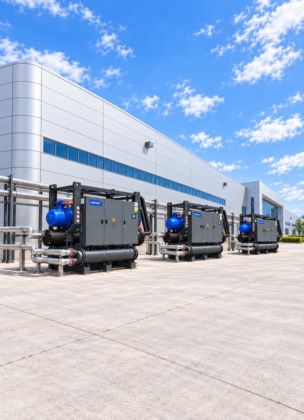

Process Cooling Systems for the Textile Industry
A textile process cooling system combines chillers, dry coolers, intermediate heat exchangers, buffer tanks and controls to cool dye baths at the rate required by the recipe, meet the continuous cooling demand of synthetic-fibre lines and condition production areas at different temperature levels. Carnot designs each system for the facility, from machine-recipe analysis to heat recovery.
Sector Overview & Process Demands
A textile process cooling system combines chillers, dry coolers, intermediate heat exchangers, buffer tanks and controls to cool dye baths at the rate required by the recipe, meet the continuous cooling demand of synthetic-fibre lines and condition production areas at different temperature levels. Carnot designs each system for the facility, from machine-recipe analysis to heat recovery.
Temperature control in textile production directly affects dyeing repeatability, product quality, production time and machine performance. High and variable heat loads from dyeing machines, finishing lines, synthetic-fibre production, printing processes and auxiliary equipment must be removed in a controlled way.
Carnot develops central and process-level cooling systems for yarn, weaving, knitting, dyeing, printing and finishing facilities. Chillers, dry coolers, free cooling, heat exchangers, pump and tank groups and controls are engineered to provide the temperature, flow rate and capacity required by different production lines while using energy efficiently.
Critical Operational Requirements
Why Is Process Cooling Important in Textile Production?
Textile cooling loads vary by process. Dyehouses need controlled cooling of hot process baths, while synthetic-fibre extrusion, drawing and winding need continuous cooling. Insufficient or poorly controlled cooling can cause temperature deviations from dye recipes and the issues listed below:
- Color tone differences
- Longer batch cycles
- Disruption of fabric and yarn quality
- The rise of machine oil temperature
- Overheating of electronic and mechanical equipment
- Reduced production capacity
- Increased water and energy consumption
- A properly engineered system keeps dye recipes repeatable and meets changing cooling loads reliably.
Which Textile Processes Are Served?
Each process has different temperatures, cooling times, flows and operating patterns. Synthetic-filament quench air is typically conditioned to 18–22 °C at stable humidity; extruders, godets and winding equipment use 15–25 °C process water and often run continuously. Spinning and weaving halls may need 24–28 °C and 55–65% relative humidity, supplied through air-handling units using 12–16 °C water. Size the system from real heat loads and simultaneous operation at each stage rather than machine count alone.
- Jet and overflow dyeing machines
- Yarn dyeing machines
- Fabric dyeing and washing lines
- Printing and digital printing machines
- Auxiliary circuits for stenter and finishing lines
- Synthetic-fibre and filament production
- Polymer extrusion lines
- Drawing, texturing and winding machines
- Calender and coating lines
- Oil and hydraulic-circuit cooling
- Machine and electrical-panel cooling
- Process-air and air-handling units
- Humidity control systems
- Auxiliary circuits of compressor and vacuum pumps
- Central process water systems
- Wastewater and process heat recovery
System Design & Capacity Calculation
Engineering & Sizing Criteria
How Is a Textile Process Cooling System Designed?
Cooling load varies through the day. When several dyeing machines enter their cooling stages together, they create short peaks; synthetic-fibre plants generally have a more continuous load profile.
| Design Parameter | Engineering Significance |
|---|---|
Process or product quantity | Determines the total heat to be removed. |
Starting and target temperature | Determines cooling energy and how the stages are divided. |
Cooling time and rate limit | Determines the required instant capacity directly. |
Number of simultaneous machines | Determines the central plant peak load. |
Minimum and maximum load | Affects compressor staging and part-load efficiency. |
Process-fluid properties | It determines the selection of heat exchanger, pumps and materials. |
Water quality | Affects exchanger and pipework heat-transfer performance. |
Flow and pressure loss | Affects pump selection and energy consumption. |
External environment conditions | Determines the capacity and free cooling potential of the tower/dry cooler. |
Required operating continuity | Determines standby and buffer-storage needs. |
Capacity Calculation & Thermodynamic Formula
How Is Dyehouse Cooling Capacity Calculated?
Q (kJ) = m × cp × ΔT | P (kW) = Q / t (s)
Worked Engineering Example
Example: 20,000 kg of dye liquor (cp=4.186 kJ/kg·K) from 80 °C to 40 °C (ΔT=40 °C) in 60 minutes (3,600 s): Q = 3,348,800 kJ -> P = 930.2 kW average thermal capacity.
Staged bath cooling (tower from 80 °C to 45 °C, then chiller from 45 °C to 40 °C) reduces the required chiller load from 930 kW to about 116 kW.
Energy Optimization
Share machine recipes to assess simultaneous loads and staged-cooling options.
Energy Consumption & Annual Operating Cost Analysis
1,000 kW Textile Dyehouse Annual Energy Simulation
Theoretical full-load comparison for an example textile facility with 1,000 kW cooling demand operating 6,000 hours/year.
Scenario comparison table
| System | COP | Compressor power | Annual consumption |
|---|---|---|---|
| Reference chiller system | 4.50 | 222.2 kW | 1,333,200 kWh |
| High-efficiency Carnot system | 5.75 | 173.9 kW | 1,043,400 kWh |
| Theoretical saving / difference | — | 48.3 kW | 289,800 kWh (21.7%) |
| Annual cost advantage | — | €0.12/kWh | Approximately €34,800 |
Annual Electricity Savings
289,800 kWh
21.7% theoretical reduction in compressor use
Annual Cost Advantage
~34,800 €
Calculated at €0.12/kWh reference electricity rate
Theoretical Power Difference
48.3 kW
Reference COP 4.50 / Carnot COP 5.75
Note: This calculation compares compressor power at 6,000 hours of full load. Actual annual savings will depend on plant load profiles, process temperatures, pump and fan modulation, local weather data, and economizer hours.
Related products
Kalter Series Dry Cooler
Rejects heat to outdoor air in the first stage of dyehouse cooling.
- Capacity
- 90–1,800 kW
- System
- Dry cooler
Thule Series Air-Cooled Chiller
Supplies water or glycol to textile processes without a cooling tower.
- Capacity
- 2–2,000 kW
- Compressor
- Scroll / screw
Tundra Series Water-Cooled Chiller
Provides stable cooling for central textile lines with long operating hours.
- Capacity
- 30–4,000 kW
- Compressor
- Scroll / screw
ZERO Series Chiller
Provides efficient low-GWP cooling for textile processes.
- Capacity
- 10–1,800 kW
- Refrigerant
- R1234ze
Fusion Series Free Cooling Unit
Pre-cools process water to reduce mechanical cooling demand.
- Capacity
- 15–2,000 kW
- Operating principle
- Free cooling
Technical Questions About Textile Cooling Systems
Detailed engineering answers on system sizing, capacity calculations, water temperatures, and Carnot equipment.
Let's engineer solutions tailored to your needs
By analyzing your process and operational data against engineering criteria, we determine capacity, system configuration, and implementation details. Let's turn your technical requirements into the right equipment selection and an actionable system design.