
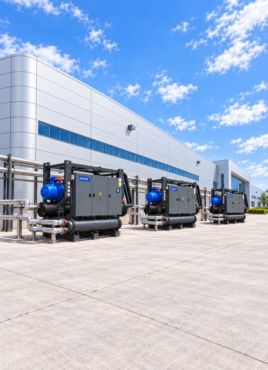

Cooling Systems for Die Casting and Metal Injection Processes
A die casting and metal injection cooling system combines chillers, dry coolers, buffer tanks, heat exchangers and controls to remove cyclical and pulsed heat from mould, hydraulic-oil and induction circuits through closed-loop process water. It also monitors water loss and low-flow conditions. Carnot designs each system for the facility, from machine-cycle analysis to safety scenarios.
Sector Overview & Process Demands
A die casting and metal injection cooling system combines chillers, dry coolers, buffer tanks, heat exchangers and controls to remove cyclical and pulsed heat from mould, hydraulic-oil and induction circuits through closed-loop process water. It also monitors water loss and low-flow conditions. Carnot designs each system for the facility, from machine-cycle analysis to safety scenarios.
Cooling in die casting and metal injection directly affects part quality, mould life, cycle time and production safety. High heat loads from moulds, hydraulic circuits, induction systems, furnaces and auxiliary equipment must be removed in a controlled way.
Carnot develops central and machine-level process cooling systems for aluminium and zinc-alloy die casting machines, foundry lines, induction furnaces and metalworking plants. Chillers, dry coolers, free cooling, heat exchangers, pump and tank groups and controls are engineered for stable flow, controlled temperature and continuous operation under high, pulsed thermal loads.
Critical Operational Requirements
Why Is Cooling Important in Die Casting?
In die casting and metal injection, the mould surface contacts hot molten metal on every cycle. If the transferred heat is not removed at the right rate, cycle time rises, part quality suffers and thermal stress builds in the mould. A properly designed process cooling system controls mould temperature distribution.
- Supports repeatability of cycle times.
- Provides controlled operation of part solidification.
- Helps protect surface finish and dimensional quality.
- Keeps hydraulic-oil temperature within operating limits.
- It protects critical equipment such as induction coil and power electronics.
- Responds to sudden changes in heat load.
- Reduces risk of unplanned downtime and equipment damage.
- Keeps energy consumption under control in variable production loads.
Which Die Casting Processes Are Served?
Temperature, flow, pressure, water quality and safety requirements vary by application. Select the system from the actual heat to be removed and the production cycle, not only the machine’s nominal power.
- Aluminium high-pressure die casting (HPDC) machines
- Zamak injection machines
- Low pressure casting processes
- Gravity and permanent-mould casting lines
- Sand casting auxiliary systems
- Casting mould and core cooling
- Mould temperature-controller cooling circuits
- Piston and chamber cooling circuits
- Induction furnace and induction coil cooling
- Furnace power electronics and electrical-panel cooling
- Hydraulic oil cooling
- Vacuum systems
- Lubrication and die spraying systems
- Robotic cell and automation equipment
- Part cooling and quenching tanks
- Central process water systems
- Compressor and auxiliary equipment circuits
System Design & Capacity Calculation
Engineering & Sizing Criteria
How Is a Die Casting Cooling System Designed?
Thermal load changes through mould closing, metal injection, solidification, part removal and die spraying. Where many machines operate, overlapping cycles can create short peak loads on the central system.
| Design Parameter | Engineering Significance |
|---|---|
Machine and die load | Determines the required total cooling capacity. |
Parts and metal quantity | Determines the heat transferred to the system in each cycle. |
Cycle Time | Determines average and instantaneous cooling load. |
Mold water temperature | It affects solidification speed and mold thermal balance. |
Flow and channel structure | It determines the heat transfer performance in the mold. |
Minimum and maximum load | Affects chiller staging and part-load efficiency. |
Peak-load duration | Used to size buffer storage and total capacity. |
Water quality | Determines the risk of residue and blockage in narrow mold channels. |
Circuit pressure | Must stay within pump and mould-circuit pressure ratings. |
Redundancy requirement | Keeps critical equipment cooled without interruption. |
Circuit integrity | It is important for early detection of leakage and water loss. |
External environment conditions | Affects chiller and free cooling performance. |
Capacity Calculation & Thermodynamic Formula
How Is Die Casting Cooling Capacity Calculated?
The heat carried by a closed water circuit is calculated using the following basic equation:
Q = ṁ × cp × ΔT
Worked Engineering Example
For a water circuit, Q (kW) = 1.163 × Flow (m³/h) × ΔT (°C). At 120 m³/h and a 5 °C inlet-to-outlet difference, Q = 1.163 × 120 × 5 = 697.8 kW, or approximately 698 kW of theoretical heat load. Final chiller sizing also considers simultaneous machines, hydraulic-oil and induction circuits, pipework gains, peak loads and expansion. For a new plant, casting throughput gives an initial estimate: aluminium releases about 800 kJ/kg between a 700 °C melt and a 300 °C part outlet, including latent heat; zinc alloy releases about 200 kJ/kg. A machine casting 150 kg/h of aluminium therefore releases about 150 × 800 ÷ 3,600 ≈ 33 kW at the mould. Some heat escapes through the surface, spraying and radiation, so the water share depends on mould design. Hydraulic-oil cooling is often 10–20% of installed hydraulic power. In an existing plant, measure flow and inlet/outlet temperatures together on main and critical machine circuits; pipe temperature alone cannot establish capacity reliably.
Total central plant capacity must include machine simultaneity, safety margins, buffer storage and future expansion plans.
Energy Optimization
Share your machine-cycle data to assess peak load and buffer-tank capacity.
Energy Consumption & Annual Operating Cost Analysis
1,200 kW Die Casting Plant Annual Energy Simulation
Theoretical full-load comparison for an example die casting facility with 1,200 kW cooling demand operating 6,000 hours/year.
Scenario comparison table
| System | COP | Compressor power | Annual consumption |
|---|---|---|---|
| Reference chiller system | 4.50 | 266.7 kW | 1,600,200 kWh |
| High-efficiency Carnot system | 5.75 | 208.7 kW | 1,252,200 kWh |
| Theoretical saving / difference | — | 58.0 kW | 348,000 kWh (21.7%) |
| Annual cost advantage | — | €0.12/kWh | Approximately €41,800 |
Annual Electricity Savings
348,000 kWh
21.7% theoretical reduction in compressor use
Annual Cost Advantage
~41,800 €
Calculated at €0.12/kWh reference electricity rate
Theoretical Power Difference
58.0 kW
Reference COP 4.50 / Carnot COP 5.75
Note: This calculation compares compressor power at 6,000 hours of full load. Actual annual savings will depend on plant load profiles, process temperatures, pump and fan modulation, local weather data, and economizer hours.
Related products
Thule Series Air-Cooled Chiller
Supplies water or glycol to the casting process without a cooling tower.
- Capacity
- 2–2,000 kW
- Compressor
- Scroll / screw
Tundra Series Water-Cooled Chiller
Provides stable capacity for high-load central foundry systems.
- Capacity
- 30–4,000 kW
- Compressor
- Scroll / screw
ZERO Series Chiller
A low-GWP refrigerant option for foundry process cooling.
- Capacity
- 10–1,800 kW
- Refrigerant
- R1234ze
Fusion Series Free Cooling Unit
Pre-cools process water and reduces compressor load when outdoor air permits.
- Capacity
- 15–2,000 kW
- Operating principle
- Free cooling
Kalter Series Dry Cooler
Rejects heat from hydraulic oil and auxiliary foundry circuits to outdoor air.
- Capacity
- 90–1,800 kW
- System
- Dry cooler
Technical Questions About Foundry & Die Casting Cooling Systems
Detailed engineering answers on system sizing, capacity calculations, water temperatures, and Carnot equipment.
Let's engineer solutions tailored to your needs
By analyzing your process and operational data against engineering criteria, we determine capacity, system configuration, and implementation details. Let's turn your technical requirements into the right equipment selection and an actionable system design.