
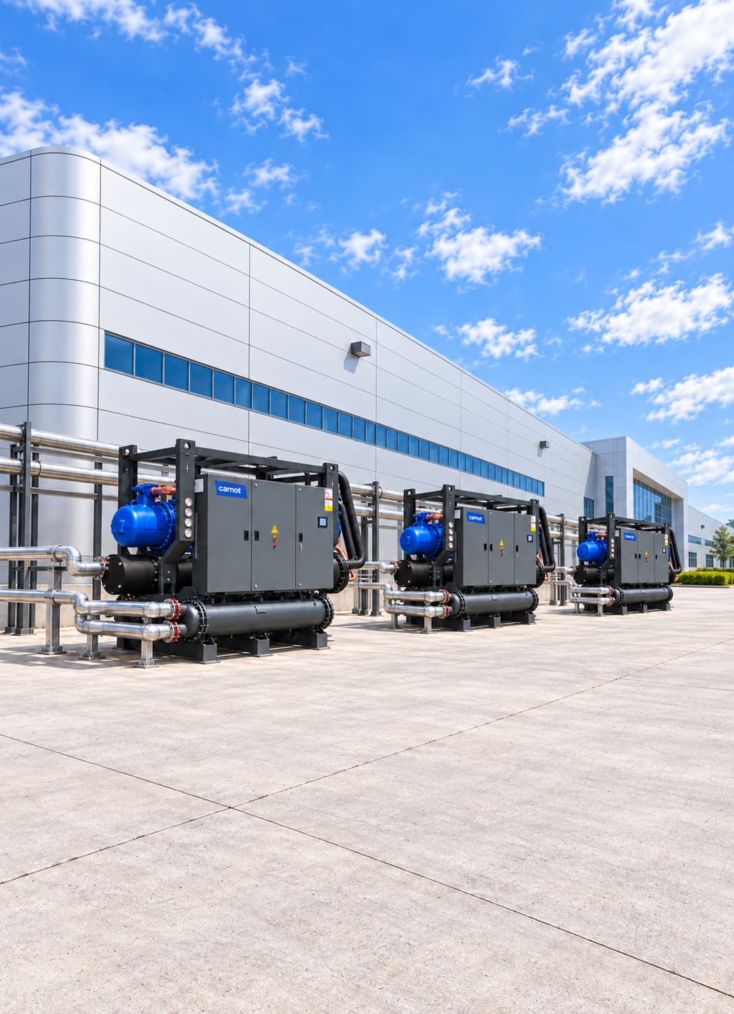


Process Cooling Systems for the Plastics and Rubber Industry
A plastics and rubber process cooling system combines a central chiller that supplies injection moulds, extrusion calibration tanks, hydraulic units and rubber mixers at the right temperature with mould temperature controllers that provide precise control for each mould. Carnot sizes these systems for the facility, from production throughput in kg/hour to dew-point control.
Sector Overview & Process Demands
A plastics and rubber process cooling system combines a central chiller that supplies injection moulds, extrusion calibration tanks, hydraulic units and rubber mixers at the right temperature with mould temperature controllers that provide precise control for each mould. Carnot sizes these systems for the facility, from production throughput in kg/hour to dew-point control.
Temperature control in plastics and rubber production directly affects product quality, cycle time, mould life and production continuity. Poor heat removal from moulds, hydraulic oil, extruders and auxiliary equipment can cause surface defects, dimensional variation, longer cycles and higher scrap rates.
Carnot develops central and machine-level process cooling systems for plastic injection, extrusion, blow moulding, PET preforms and rubber production. Systems combining chillers, dry coolers, free cooling and Molder Series mould temperature controllers target stable fluid temperature, the right flow rate, energy efficiency and uninterrupted production.
Critical Operational Requirements
Why Is Process Cooling Important in Plastics and Rubber?
Heat must be removed from formed plastic at a controlled rate so the part can leave the mould at the required quality. Changes in cooling-water temperature, flow or pressure create uneven mould-surface temperatures. A properly engineered process cooling system keeps these conditions stable.
- Keeps mould temperature within its specified operating range.
- Provides repeatability of production cycles.
- Controls cooling and cycle time.
- Protects product quality and dimensional stability.
- Prevents excessive heating of hydraulic oil and auxiliary equipment.
- Reduces unplanned downtime and process scrap.
- Variable production loads limit unnecessary energy consumption.
Which Plastics and Rubber Processes Are Served?
PET preform machines use 8–12 °C mould water at high flow; with 48–144 cavities per mould, they can create a major mould-cooling load that drives chiller sizing. Extrusion vacuum-calibration tanks for pipes and profiles need 12–18 °C water, while film-line chill rolls operate at 15–25 °C. In rubber plants, cooling load comes mainly from Banbury mixer rotor and chamber circuits at 20–35 °C and hydraulic units on vulcanisation presses; vulcanisation moulds are heated. Temperature, flow, pressure and water quality differ by process, so size for actual heat removal rather than machine power alone.
- Plastic injection machines
- PET preform and bottle production lines
- Plastic extrusion lines and calibration tanks
- Film lines and chill rolls
- Blow-moulding and thermoforming machines
- Plate, pipe and profile production
- Rubber mixers (Banbury) and calender lines
- Hydraulic circuits of rubber presses and vulcanization lines
- Injection moulds and mould-temperature-control circuits
- Hydraulic oil cooling circuits
- Central mould-cooling systems
System Design & Capacity Calculation
Engineering & Sizing Criteria
How Is a Plastics Process Cooling System Designed?
Use actual operating conditions as well as machine ratings. Size capacity from process load, simultaneous operation, target water temperature, design temperature difference, annual operating hours and planned expansion.
| Design Parameter | Engineering Significance |
|---|---|
Processing material (kg/h) and polymer type | Affects mould cooling load and target mould temperature. |
Process thermal load | Determines the required capacity of chiller and auxiliary equipment. |
Fluid inlet-out temperature | Determines heat transfer capacity and process stability. |
Number of temperature circuits | Determines whether mould (chiller) and hydraulic (dry cooler) circuits should be separated. |
Design flow | It is necessary for sufficient heat transfer in mould and machines. |
Pressure loss | Determines pump head and energy consumption. |
Simultaneous working rate | Prevents unnecessary high or insufficient capacity selection. |
Minimum and maximum load | Determines compressor stepping and partial load efficiency. |
Ambient dew point | Determines condensation risk and the lowest safe mould-water temperature. |
Water quality | It determines the life of heat exchanger, mold channels and installation. |
External environment conditions | Affects chiller selection and free-cooling potential. |
Redundancy requirement | Provides continuous cooling in critical processes. |
Capacity Calculation & Thermodynamic Formula
How Is Process Cooling Capacity Calculated?
The heat carried by the water circuit is calculated using the following basic equation:
Q = ṁ × cp × ΔT
Worked Engineering Example
For a water circuit, Q (kW) = 1.163 × Flow (m³/h) × ΔT (°C). At 50 m³/h and a 5 °C inlet-to-outlet difference, Q = 1.163 × 50 × 5 = 290.75 kW, or about 291 kW. Final chiller capacity also depends on simultaneous machines, ambient conditions, pipework heat gains, load changes and growth. For a new plant, material throughput provides an initial estimate: polymer heat removal is roughly 0.10–0.15 kWh/kg, about 0.14 kWh/kg for PP and PE including crystallisation, 0.12 for PET and 0.10 for PS and ABS. At 500 kg/h of PP, mould cooling is about 500 × 0.14 = 70 kW; add hydraulic-oil cooling, often 10–20% of installed machine power, and auxiliaries. A rough guide is 1 kW of chiller capacity per 7–10 kg/h of plastic. Oversizing increases cycling and cost; undersizing raises water temperature, cycle time and defect risk.
Combining central chillers with dedicated Molder units at each press stabilises cycle time, reduces scrap and optimises energy use.
Sector Reference Data
Polymer Mould Temperatures and Fluid Selection
| Polymer | Typical mould temperature | Supply fluid |
|---|---|---|
| PE,PP | 10–40 °C | Chilled water |
| PET preform | 8–15°C | Chilled water |
| PS, ABS | 40–80°C | Mould temperature controller (water) |
| PA, POM | 80–100°C | Mould temperature controller (water/oil) |
| PC, PMMA | 80–120°C | Mould temperature controller (pressurised water/oil) |
| Rubber (vulcanization) | 150–200 °C | Heating; cooling only for hydraulics and mixers |
Energy Optimization
Share your machine list and production throughput in kg/hour for a chiller and mould-controller capacity plan.
Energy Consumption & Annual Operating Cost Analysis
500 kW Plastic Injection Facility Annual Energy Simulation
Theoretical full-load comparison for a plastic injection moulding plant with 500 kW cooling demand operating 4,000 hours/year.
Scenario comparison table
| System | COP | Compressor power | Annual consumption |
|---|---|---|---|
| Reference chiller system | 4.50 | 111.1 kW | 444,400 kWh |
| High-efficiency Carnot system | 5.75 | 87.0 kW | 348,000 kWh |
| Theoretical saving / difference | — | 24.1 kW | 96,400 kWh (21.7%) |
| Annual cost advantage | — | €0.12/kWh | Approximately €11,600 |
Annual Electricity Savings
96,400 kWh
21.7% theoretical reduction in compressor use
Annual Cost Advantage
~11,600 €
Calculated at €0.12/kWh reference electricity rate
Theoretical Power Difference
24.1 kW
Reference COP 4.50 / Carnot COP 5.75
Note: This calculation compares compressor power at 4,000 hours of full load. Actual annual savings will depend on plant load profiles, process temperatures, pump and fan modulation, local weather data, and economizer hours.
Engineering & Sizing Checklist
Let’s Design the Cooling System for Your Process
Carnot engineers the complete system for your operating conditions, from process-load assessment and chiller, mould-controller and hydraulic-equipment selection to controls and annual energy analysis. The information below is enough for an initial review:
- 1Production process and number of machines
- 2Material type and hourly throughput
- 3Mould temperatures and controller needs
- 4Necessary cooling capacity
- 5Fluid inlet-out temperatures
- 6Process flow and pressure need
- 7Daily and annual working time
- 8Facility location
- 9Current chiller, tank and pump information
- 10Planned capacity expansion
Request Process Cooling Design
Share your facility specs, and our engineering team will prepare your energy and capacity simulation.
Related products
Molder Series Mould Temperature Controller
Controls mould temperature precisely through water or oil circulation.
- Capacity
- 5–60 kW
- Control
- PID
Thule Series Air-Cooled Chiller
Supplies process water to plastics production without a cooling tower.
- Capacity
- 2–2,000 kW
- Compressor
- Scroll / screw
Tundra Series Water-Cooled Chiller
Provides stable capacity for high-load central process circuits.
- Capacity
- 30–4,000 kW
- Compressor
- Scroll / screw
ZERO Series Chiller
A low-GWP cooling option for plastics and rubber processes.
- Capacity
- 10–1,800 kW
- Refrigerant
- R1234ze
Fusion Series Free Cooling Unit
Uses suitable outdoor air to reduce cooling demand on year-round lines.
- Capacity
- 15–2,000 kW
- Operating principle
- Free cooling
Kalter Series Dry Cooler
Removes heat from hydraulic oil and rubber-mixer circuits.
- Capacity
- 90–1,800 kW
- System
- Dry cooler
Technical Questions About Plastics & Rubber Cooling Systems
Detailed engineering answers on system sizing, capacity calculations, water temperatures, and Carnot equipment.
Let's engineer solutions tailored to your needs
By analyzing your process and operational data against engineering criteria, we determine capacity, system configuration, and implementation details. Let's turn your technical requirements into the right equipment selection and an actionable system design.