
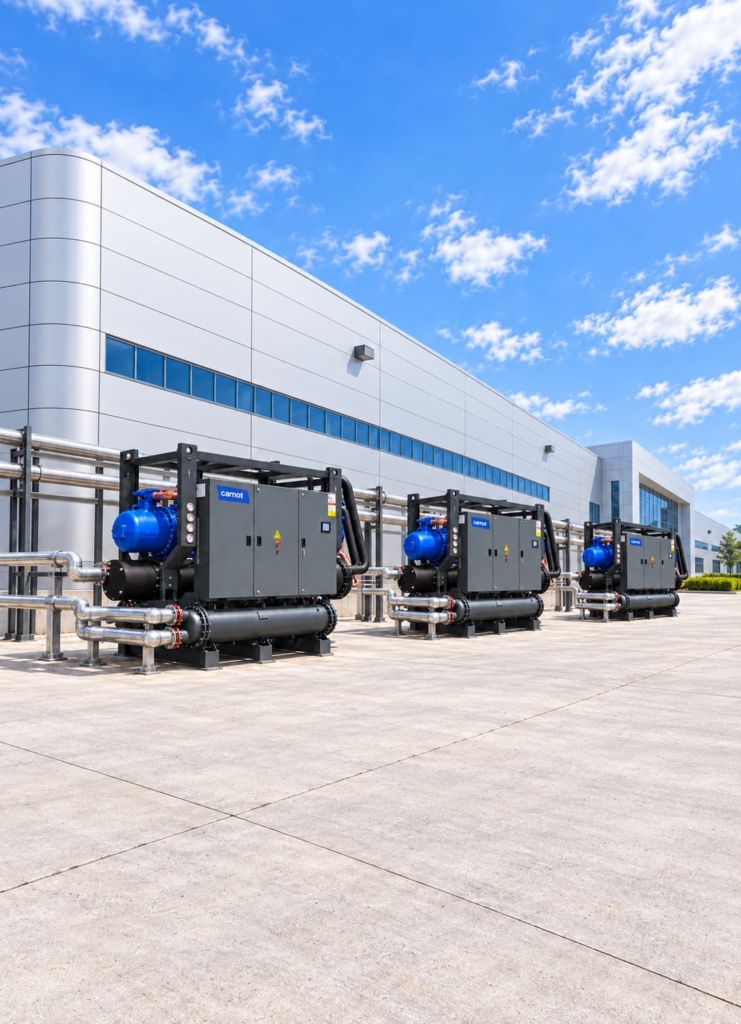


Process Cooling Systems for Pharmaceutical and Chemical Industry
A pharmaceutical and chemical process cooling system combines chillers, dry coolers, heat exchangers and controls to supply reactor jackets, cleanroom air-handling units and low-temperature glycol circuits down to −45 °C with precise temperature profiles. It records time-stamped operating data and runs with N+1 redundancy. Carnot designs each system around the facility’s GMP documentation needs and hazardous-area boundaries.
Sector Overview & Process Demands
A pharmaceutical and chemical process cooling system combines chillers, dry coolers, heat exchangers and controls to supply reactor jackets, cleanroom air-handling units and low-temperature glycol circuits down to −45 °C with precise temperature profiles. It records time-stamped operating data and runs with N+1 redundancy. Carnot designs each system around the facility’s GMP documentation needs and hazardous-area boundaries.
Temperature control in pharmaceutical and chemical production directly affects reaction rate, product quality, process safety and production time. Poor control of heat loads in reactors, process tanks, condensers and filling lines can cause deviations from the process recipe, make reactions harder to manage and reduce production capacity.
Carnot develops central and process-level cooling systems for pharmaceuticals, active pharmaceutical ingredients (APIs), cosmetics, paints, resins and other chemical processes. Chillers, dry coolers, free cooling, pump and tank groups, heat exchangers and controls are designed for precise temperature control, traceable operating data and production continuity.
Critical Operational Requirements
Why Is Cooling Critical in Pharmaceutical and Chemical Processes?
Heat released during a chemical reaction can rapidly raise reactor temperature. In exothermic processes, insufficient cooling capacity or flow makes the reaction harder to control. Pharmaceutical production also requires temperature to stay within the specified recipe range for product quality, batch repeatability and GMP records. A properly designed system follows the required reactor temperature profile.
- Safely removes heat from exothermic reactions.
- Keeps batch times and production recipes repeatable.
- Protects product quality and process stability.
- Monitors and records critical temperature, pressure and flow values.
- Fits sudden changes in production load.
- Provides continuity of production during maintenance or failure.
- Limits unnecessary compressor, pump and fan energy use.
Which Pharmaceutical and Chemical Processes Are Served?
Each application differs in temperature range, fluid properties, load changes and safety needs. Design must follow process thermal behaviour and controls, not total capacity alone. In pharmaceutical plants, cleanroom air-handling units can account for more than half the chiller load. Cleanrooms within ISO 14644 and EU GMP Annex 1 commonly operate at 20–24 °C and 45–55% relative humidity; dehumidification coils may need 6/12 °C water. Cleanroom HVAC can run continuously while reactor loads change with batches. When both share a chiller group, stage capacity for the cleanroom base load and allow peak capacity for process duty. Redundancy is particularly important where cleanroom temperature or humidity deviations affect GMP compliance. Water for injection (WFI) circulates at 80 °C and is cooled to 20–25 °C at points of use, adding another continuous chiller load.
- Carnot process cooling systems are used in the following pharmaceutical and chemical applications:
- Cooling of reactor jackets and temperature control units (TCU)
- Mixing and process tanks
- Exothermic chemical reactions
- Active pharmaceutical ingredient (API) production
- Crystallization processes
- Fermentation and bioprocess applications
- Solvent recovery systems
- Distillation condensers
- Vacuum systems
- Cleanroom air-handling units
- Filling and packaging lines
- Cosmetic production
- Paint and coating production
- Resin and polymerization processes
- Detergent and cleaning chemicals
- Laboratory and pilot production systems
- Purified-water and WFI point-of-use coolers
- Low-temperature water-glycol systems
- Production area and equipment cooling
- Cleanroom air-handling cooling
System Design & Capacity Calculation
Engineering & Sizing Criteria
How Is a Pharmaceutical Process Cooling System Designed?
In pharmaceutical and chemical plants, peak instantaneous load matters as much as average load. A batch reaction can release a large amount of heat during one short stage; sizing from total daily energy alone may leave that peak unmet.
| Design Parameter | Engineering Significance |
|---|---|
Reaction heat | Determines total and instantaneous thermal load to be removed from the process. |
Batch duration | Determines the required cooling capacity and storage volume. |
Temperature profile | It determines the control of heating, waiting and cooling steps. |
Cooling time | Determines the required instant capacity directly. |
Reactor jacket area | Limits the rate of heat transfer to the process fluid. |
Clean room base load | Determines the chiller stepping and minimum capacity. |
Fluid properties | It determines the selection of pump, exchanger, seal and installation. |
Minimum operating temperature | Determines glycol concentration and chiller operating conditions. |
Flow and pressure loss | It affects heat transfer performance and pump consumption. |
Material compatibility | Determines the risk of corrosion and sealing. |
Redundancy requirement | Maintains cooling for critical processes. |
Data logging and traceability | Supports validation of critical parameters under GMP. |
Hazardous-area classification | Determines equipment location and specifications for components within the area. |
Capacity Calculation & Thermodynamic Formula
How Is Reactor Cooling Capacity Calculated?
Reactor load includes reaction heat, product temperature change, agitator energy and ambient heat gains. Sensible heat that must be removed to cool the product within a defined time is calculated as follows:
Q = m × cp × ΔT
Worked Engineering Example
Q is the energy to remove, m is product or mixture mass, cp is its specific heat and ΔT is the initial-to-target temperature difference. Divide energy by the required cooling time for average capacity; calculate the instantaneous heat release of exothermic reactions separately. For a water circuit, Q (kW) = 1.163 × Flow (m³/h) × ΔT (°C). If 60 m³/h circulates through a reactor jacket with a 6 °C inlet-to-outlet difference, Q = 1.163 × 60 × 6 = 418.68 kW.
The theoretical heat load transferred in this circuit is approximately 419 kW. Actual process cooling is also limited by reactor-jacket area, heat-transfer coefficient, product viscosity and the temperature difference between jacket and product. A larger chiller alone may not shorten cooling time.
Energy Optimization
Request capacity staging and redundancy analysis for your reactor and cleanroom loads.
Energy Consumption & Annual Operating Cost Analysis
800 kW Pharmaceutical & Chemical Plant Annual Energy Simulation
Theoretical full-load comparison for an example pharmaceutical facility with 800 kW cooling demand operating 6,000 hours/year.
Scenario comparison table
| System | COP | Compressor power | Annual consumption |
|---|---|---|---|
| Reference chiller system | 4.50 | 177.8 kW | 1,066,800 kWh |
| High-efficiency Carnot system | 5.75 | 139.1 kW | 834,600 kWh |
| Theoretical saving / difference | — | 38.7 kW | 232,200 kWh (21.7%) |
| Annual cost advantage | — | €0.12/kWh | Approximately €27,900 |
Annual Electricity Savings
232,200 kWh
21.7% theoretical reduction in compressor use
Annual Cost Advantage
~27,900 €
Calculated at €0.12/kWh reference electricity rate
Theoretical Power Difference
38.7 kW
Reference COP 4.50 / Carnot COP 5.75
Note: This calculation compares compressor power at 6,000 hours of full load. Actual annual savings will depend on plant load profiles, process temperatures, pump and fan modulation, local weather data, and economizer hours.
Related products
ZERO Series Chiller
Provides efficient low-GWP cooling for pharmaceutical and chemical processes.
- Capacity
- 10–1,800 kW
- Refrigerant
- R1234ze
Thule Series Air-Cooled Chiller
Supplies process water or glycol without a cooling tower.
- Capacity
- 2–2,000 kW
- Compressor
- Scroll / screw
Tundra Series Water-Cooled Chiller
Serves the cleanroom HVAC base load in central systems.
- Capacity
- 30–4,000 kW
- Compressor
- Scroll / screw
Fusion Series Free Cooling Unit
Reduces mechanical cooling demand and compressor hours when outdoor air permits.
- Capacity
- 15–2,000 kW
- Operating principle
- Free cooling
Kalter Series Dry Cooler
Removes heat from condenser, vacuum and auxiliary equipment circuits.
- Capacity
- 90–1,800 kW
- System
- Dry cooler
Technical Questions About Pharmaceutical & Chemical Cooling Systems
Detailed engineering answers on system sizing, capacity calculations, water temperatures, and Carnot equipment.
Let's engineer solutions tailored to your needs
By analyzing your process and operational data against engineering criteria, we determine capacity, system configuration, and implementation details. Let's turn your technical requirements into the right equipment selection and an actionable system design.