
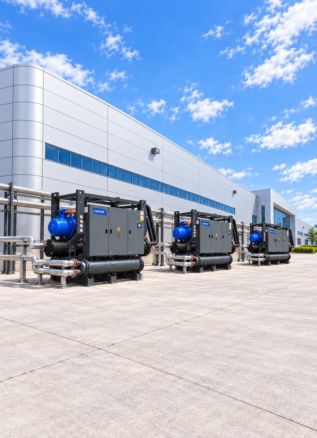


High-Efficiency Cooling Systems for Data Centers
A data centre cooling system combines chillers, dry coolers, pumps and controls to remove server heat 24/7, operate with N+1 or 2N redundancy and reduce annual energy use through free cooling. Carnot designs each system for the facility, from IT load analysis to annual energy simulation.
Sector Overview & Process Demands
A data centre cooling system combines chillers, dry coolers, pumps and controls to remove server heat 24/7, operate with N+1 or 2N redundancy and reduce annual energy use through free cooling. Carnot designs each system for the facility, from IT load analysis to annual energy simulation.
Cooling directly affects server performance, IT equipment life, facility uptime and total energy use in a data centre. Most of the electricity consumed by servers, storage, network devices, UPS systems and power electronics becomes heat that must be removed continuously throughout the year.
Carnot develops central cooling systems for IT loads ranging from conventional data centres to high-density GPU and AI infrastructure. Solutions using chillers, dry coolers, free cooling, pump groups, heat exchangers and controls are engineered with reference to EN 50600 and ASHRAE TC 9.9 thermal guidance, with a focus on part-load efficiency, controlled water temperature and redundant operation.
Critical Operational Requirements
Why Is Data Centre Cooling Critical?
Unlike many production loads, data centre cooling can be required 24 hours a day throughout the year. Critical servers and network equipment keep running even when IT load falls, so the system must operate steadily and efficiently at low and medium loads as well as at design capacity. It must keep server-inlet conditions within the operating range set out in ASHRAE TC 9.9.
- Limits mixing between hot and cold aisles.
- Meets the heat load of high density rack and GPU systems.
- Improves the part-load efficiency of chillers, pumps and fans.
- Keeps critical equipment operating with redundancy.
- Supports cooling during maintenance.
- Increases free cooling usage time.
- Provides separate monitoring of energy and water consumption.
- Helps improve PUE and WUE performance.
Which Data Centre Applications Are Served?
Rack density, IT equipment class, operating temperature, redundancy level and growth plan vary by facility. Size cooling from actual IT load and its distribution rather than total building area alone.
- Enterprise data centres
- Colocation facilities
- Cloud service data centres
- Telecommunications facilities
- Banking and finance data centers
- Public and defense facilities
- High-performance computing centres
- GPU and AI clusters
- Edge data centers
- Modular data centers
- Disaster recovery centers
- Server and network rooms
- Chilled water CRAH systems
- In-row and rear-door cooling systems
- Direct-to-chip liquid cooling infrastructures
- CDU and plant water circuits
- UPS and power electronics rooms
System Design & Capacity Calculation
Engineering & Sizing Criteria
How Is a Data Centre Cooling System Designed?
First establish current and planned IT load. Then assess how it is distributed across rooms and racks, the air or liquid cooling architecture, target Tier level, redundancy arrangement and local climate.
| Design Parameter | Engineering Significance |
|---|---|
Total IT load | Determines the basic capacity of the cooling system. |
Power density per rack | It affects the selection of air or liquid cooling architecture. |
Current and future load | Helps plan modular capacity expansion. |
Server inlet conditions | Determines the safe working environment according to ASHRAE class of IT equipment. |
Chilled water temperatures | Affects chiller efficiency and free-cooling hours. |
Facility location | Determines dry cooler and free cooling potential. |
Minimum and maximum IT load | Shows the chiller's part-load and minimum capacity requirements. |
Target Tier level | Determines whether N+1, 2N or 2(N+1) redundancy is required. |
Water usage target (WUE) | It affects air or water-cooled system preferences. |
Electrical infrastructure | It determines the backup energy architecture of the cooling system. |
Growth plan | It affects the future capacity of pipe, pump and main equipment. |
Capacity Calculation & Thermodynamic Formula
How Is Data Centre Cooling Capacity Calculated?
IT equipment electricity use is the starting point for cooling-load calculations: most of that energy becomes heat in the data hall, so a continuous 1 kW IT load produces approximately 1 kW of heat. Total facility capacity must also include the additional loads below:
Additional loads considered in the calculation:
- UPS and power distribution losses
- Lighting
- Staff in the data room
- Solar gain and heat passing through the building envelope
- Air leaks
- Heat released into the space by pumps and fans
- Auxiliary electrical rooms
- Increase in future IT capacity
- The capacity carried on the water circuit can be calculated with the following formula:
Q (kW) = 1.163 × Flow (m³/h) × ΔT (°C)
Worked Engineering Example
Example: With 250 m³/h circulating flow in the main data center cooling circuit and 6 °C supply-return difference: Q = 1.163 × 250 × 6 = 1,744.5 kW.
The theoretical cooling load transferred in this circuit is approximately 1,745 kW. Assess final capacity alongside IT load, redundancy, heat-exchanger approach temperatures and growth plans.
Energy Optimization
Request a free-cooling and annual energy simulation using hourly local climate data.
Energy Consumption & Annual Operating Cost Analysis
2,000 kW Continuous Load Data Center Annual Energy Simulation
Theoretical full-load comparison for an example data center with 2,000 kW continuous cooling load operating 8,760 hours/year.
Scenario comparison table
| System | COP | Compressor power | Annual consumption |
|---|---|---|---|
| Reference chiller system | 4.50 | 444.4 kW | 3,893,000 kWh |
| High-efficiency Carnot system | 5.75 | 347.8 kW | 3,047,000 kWh |
| Theoretical saving / difference | — | 96.6 kW | 846,000 kWh (21.7%) |
| Annual cost advantage | — | €0.12/kWh | Approximately €101,500 |
Annual Electricity Savings
846,000 kWh
21.7% theoretical reduction in compressor use
Annual Cost Advantage
~101,500 €
Calculated at €0.12/kWh reference electricity rate
Theoretical Power Difference
96.6 kW
Reference COP 4.50 / Carnot COP 5.75
Note: This calculation compares compressor power at 8,760 hours of full load. Actual annual savings will depend on plant load profiles, process temperatures, pump and fan modulation, local weather data, and economizer hours.
Related products
ZERO Series Chiller
Targets high full-load and part-load efficiency for data centre loads.
- Capacity
- 10–1,800 kW
- Refrigerant
- R1234ze
Tundra Series Water-Cooled Chiller
Provides stable cooling for continuously operating, high-capacity data centres.
- Capacity
- 30–4,000 kW
- Compressor
- Scroll / screw
Thule Series Air-Cooled Chiller
Operates without a cooling tower or condenser-water consumption.
- Capacity
- 2–2,000 kW
- Compressor
- Scroll / screw
Fusion Series Free Cooling Unit
Reduces mechanical cooling demand when outdoor conditions allow.
- Capacity
- 15–2,000 kW
- Operating principle
- Free cooling
Kalter Series Dry Cooler
Rejects heat from the facility-water or intermediate glycol loop to outdoor air.
- Capacity
- 90–1,800 kW
- System
- Dry cooler
Technical Questions About Electronics & Data Centres Cooling Systems
Detailed engineering answers on system sizing, capacity calculations, water temperatures, and Carnot equipment.
Let's engineer solutions tailored to your needs
By analyzing your process and operational data against engineering criteria, we determine capacity, system configuration, and implementation details. Let's turn your technical requirements into the right equipment selection and an actionable system design.