
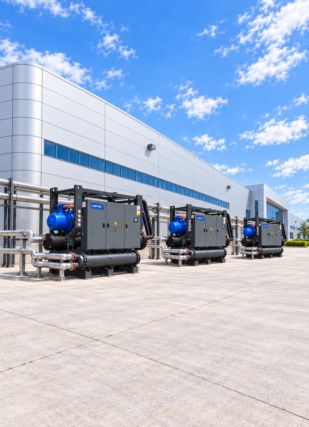

Industrial Cooling Systems for Power Generation Facilities
A power generation cooling system handles the jacket-water circuits of gas engines and generators (HT, 80–95 °C), charge-air and oil circuits (LT, 40–55 °C), turbine auxiliaries and power electronics. It uses heat recovery first, then dry coolers and, when required, chillers, with N+1 redundancy. Carnot designs each system for the facility, from the engine maker’s heat balance to emergency heat-rejection scenarios.
Sector Overview & Process Demands
A power generation cooling system handles the jacket-water circuits of gas engines and generators (HT, 80–95 °C), charge-air and oil circuits (LT, 40–55 °C), turbine auxiliaries and power electronics. It uses heat recovery first, then dry coolers and, when required, chillers, with N+1 redundancy. Carnot designs each system for the facility, from the engine maker’s heat balance to emergency heat-rejection scenarios.
Cooling in power generation facilities directly affects equipment performance, generating capacity and plant continuity. Heat from generator engines, turbines, lubrication systems, power electronics, transformers and auxiliary equipment must be removed safely and consistently.
Carnot develops central and equipment-level cooling systems for generators, cogeneration, trigeneration, biogas, gas-turbine, hydroelectric and renewable-energy plants. Chillers, dry coolers, free cooling, heat exchangers, pump and tank groups and controls are engineered to maintain capacity in high ambient temperatures, provide redundancy for critical circuits and reduce auxiliary energy use.
Critical Operational Requirements
Why Is Cooling Important in Power Generation?
When power-generation equipment runs, some fuel or electrical energy becomes useful output and some becomes heat. Heat must be removed through engine jacket water, lubrication, charge-air cooling, alternators, power electronics and auxiliaries. Insufficient cooling capacity can lead to the problems below:
- Limiting motor or turbine power (derating)
- High temperature alarms
- Change of oil viscosity
- Damage to electronic equipment
- Reduced generating capacity
- Shortening equipment life
- Unplanned plant shutdowns
- A properly engineered cooling system also helps the plant maintain full output at peak outdoor temperature and critical production load.
Which Power Generation Applications Are Served?
Battery energy storage systems keep cell temperatures around 18–30 °C. Containerised liquid-cooled systems may need a 15–25 °C glycol circuit with pulsed chiller load following charge and discharge. Solar-plant inverters can derate above 35–40 °C; dry coolers or small chillers can hold inverter rooms at 25–30 °C. Each item of equipment has its own temperature, flow, pressure and water-quality limits, so use the maker’s heat-rejection data and operating limits for design.
- Natural gas generator systems
- Diesel generator plants
- Cogeneration and trigeneration systems
- Biogas and landfill-gas engines
- Gas turbine plants
- Steam turbine auxiliary circuits
- Hydroelectric power plants
- Generator jacket water circuits
- Lubrication oil cooling systems
- Charge-air and aftercooler circuits
- Alternator and generator auxiliary cooling
- Turbine oil and bearing cooling
- Gas turbine inlet air cooling
- Transformer oil cooling auxiliary circuits
- Inverter and power electronics systems
- Solar-plant inverter rooms
- Battery energy storage systems (BESS)
- Compressor and vacuum pumps
- Control and electrical rooms
- Central facility auxiliary water systems
System Design & Capacity Calculation
Engineering & Sizing Criteria
How Is a Power Plant Cooling System Designed?
Generator or turbine electrical output alone does not determine cooling capacity. Machines with the same output can reject different amounts of heat through jacket water, oil, charge air and exhaust.
| Design Parameter | Engineering Significance |
|---|---|
Equipment heat-rejection values | Determines the required actual cooling capacity. |
HT and LT circuit temperatures | Determines heat recovery and cooling architecture. |
Minimum and maximum production load | Determines part-load operation and capacity control. |
External ambient design temperature | Affects dry-cooler and air-cooled chiller capacity. |
Flow and pressure loss | Determines pump selection and equipment performance. |
Fluid properties | Affects glycol, pump and exchanger selection. |
Water quality | Provides engine, exchanger and installation protection. |
Heat-recovery demand | Changes the net heat load that must be rejected. |
Redundancy level | Supports continuous operation of critical generation equipment. |
Electrical supply arrangement | Determines the emergency operation of the cooling system. |
Noise limits | Determines fan and equipment selection. |
Future capacity | Determines modular growth and installation sizing. |
Capacity Calculation & Thermodynamic Formula
How Is Power Generation Cooling Capacity Calculated?
Use the engine or equipment maker’s heat balance. A fixed ratio based on generator electrical output is unreliable. Heat carried by a water circuit is calculated with the formula below:
Q (kW) = 1.163 × Flow (m³/h) × ΔT (°C)
Worked Engineering Example
If 150 m³/h circulates through an auxiliary cooling loop with a 5 °C inlet-to-outlet difference, Q = 1.163 × 150 × 5 = 872.25 kW. In cogeneration, separate usable recovered heat from the total heat load. The chiller or dry cooler rejects only heat that cannot be used by the process.
The theoretical heat load carried by this circuit is approximately 872 kW. Include pump heat, exchanger approach temperatures, pipework gains and auxiliary equipment running at the same time when setting final capacity.
Energy Optimization
Share your engine heat balance and outdoor design temperature for HT/LT dry-cooler and chiller sizing.
Energy Consumption & Annual Operating Cost Analysis
900 kW Gas Engine & Cogeneration Cooling Simulation
Theoretical full-load comparison for an energy generation plant with 900 kW cooling demand operating 8,000 hours/year.
Scenario comparison table
| System | COP | Compressor power | Annual consumption |
|---|---|---|---|
| Reference chiller system | 4.50 | 200.0 kW | 1,600,000 kWh |
| High-efficiency Carnot system | 5.75 | 156.5 kW | 1,252,000 kWh |
| Theoretical saving / difference | — | 43.5 kW | 348,000 kWh (21.7%) |
| Annual cost advantage | — | €0.12/kWh | Approximately €41,800 |
Annual Electricity Savings
348,000 kWh
21.7% theoretical reduction in compressor use
Annual Cost Advantage
~41,800 €
Calculated at €0.12/kWh reference electricity rate
Theoretical Power Difference
43.5 kW
Reference COP 4.50 / Carnot COP 5.75
Note: This calculation compares compressor power at 8,000 hours of full load. Actual annual savings will depend on plant load profiles, process temperatures, pump and fan modulation, local weather data, and economizer hours.
Engineering & Sizing Checklist
Let’s Design Your Power Plant Cooling System
Carnot designs the full system for your project, from equipment heat balances to chiller, dry cooler, exchanger and pump selection, redundancy planning and annual energy and heat-recovery analysis. The information below is enough for an initial review:
- 1Type of energy production equipment
- 2Manufacturer, model and electrical power
- 3HT/LT circuit heat-rejection values and temperature limits
- 4Fluid inlet-out temperatures
- 5Flow and pressure need
- 6Heat recovery capacity and consumption profile
- 7Facility location and design outdoor temperature
- 8Daily and annual working time
- 9Available chiller, dry cooler and pump information
- 10Glycol mixture and water quality
- 11Required redundancy level
- 12Planned future capacity expansion
Request Power Plant Cooling Design
Share your facility specs, and our engineering team will prepare your energy and capacity simulation.
Related products
Kalter Series Dry Cooler
Removes heat from HT jacket water, oil and LT auxiliary circuits.
- Capacity
- 90–1,800 kW
- System
- Dry cooler
Fusion Series Free Cooling Unit
Combines dry cooling and mechanical cooling in the LT circuit.
- Capacity
- 15–2,000 kW
- Operating principle
- Free cooling
Thule Series Air-Cooled Chiller
Supplies low-temperature process water or glycol without a cooling tower.
- Capacity
- 2–2,000 kW
- Compressor
- Scroll / screw
Tundra Series Water-Cooled Chiller
Offers water-cooled capacity for high-load power generation facilities.
- Capacity
- 30–4,000 kW
- Compressor
- Scroll / screw
ZERO Series Chiller
Provides low-GWP refrigerant process cooling for power generation.
- Capacity
- 10–1,800 kW
- Refrigerant
- R1234ze
Technical Questions About Power Generation Facilities Cooling Systems
Detailed engineering answers on system sizing, capacity calculations, water temperatures, and Carnot equipment.
Let's engineer solutions tailored to your needs
By analyzing your process and operational data against engineering criteria, we determine capacity, system configuration, and implementation details. Let's turn your technical requirements into the right equipment selection and an actionable system design.